
Ozone Detector Placement: Where to Mount for Reliable Readings
Ozone Detector Placement: Where to Mount for Reliable Readings
You can buy an accurate ozone analyzer, calibrate it on schedule, and still get misleading numbers—because the instrument is sitting in the wrong place. Ozone is a dense, reactive gas that stratifies quickly, decays on contact with surfaces, and mixes poorly in dead-air zones. Placement decides whether your readings represent the room, the process, or just the pocket of air immediately around the sensor housing.
This guide covers the practical rules for siting a gas ozone monitor, the mistakes that quietly corrupt data, and how placement differs for safety, process, and dissolved ozone applications.
Why Placement Changes the Measurement
Ozone has a density of roughly 2.14 kg per cubic metre at standard conditions, about 1.6 times that of air. In a still room it tends to settle, and in a ventilated room the exhaust path dominates the distribution. Two monitors calibrated to the same standard can read 0.05 ppm and 0.15 ppm in the same room simply because one is at 1.5 m in the occupied zone and the other is at ceiling level near a supply diffuser.
The second effect is surface loss. Ozone decomposes on contact with almost any surface, and the reaction accelerates with temperature, humidity, and dirt. Long, narrow, or rough sample lines act as ozone scrubbers: a few metres of small-bore tubing or a clogged filter can remove a measurable fraction of the ozone before it reaches the sensing cell.
General Placement Rules for Gas Phase Ozone
Mount at the breathing zone
For worker safety, mount the sample inlet at 1.2–1.7 m above the floor—the head height of a standing or seated worker. Ceiling-mounted detectors look tidy but report air nobody is breathing. Where the process is the hazard, the breathing zone near the process, not the room average, is the number that matters.
Stay clear of the immediate source but inside the plume path
A detector mounted directly on the housing of an ozone generator will alarm constantly and tell you nothing about exposure. A detector placed across the room in a corridor will never trigger. The useful position is where the expected leak or off-gas plume will travel—downwind of the source under normal ventilation, at a distance consistent with the room's airflow pattern.
Avoid stagnant pockets and short-circuit paths
Corners behind equipment, ceiling voids, and the space above false ceilings hold stale air. Equally, the straight line between a supply diffuser and a return grille carries fresh air that has barely mixed with the room. Both give a false picture. Smoke-pencil or thermal-anemometer testing of the room confirms where air actually moves.
Respect fan, door, and duct effects
Doors that open during shift changes, local exhaust hoods, and portable fans all reshape the plume. If occupancy changes the airflow, a single fixed detector may not cover the room. Multiple detectors with a shared alarm, or a portable unit used for spot checks around the fixed one, resolve this.
Sample Line Design
For extractive systems, the sample line is part of the measurement. Keep it as short as practical, use ozone-compatible materials such as PTFE or stainless steel, and avoid elbows and dead legs. Sample flow must be high enough that transport delay stays within the alarm response time you need—a 30-metre line at low flow can add a minute or more between the leak and the alarm. Filters are necessary in dusty plants but must be changed on a defined schedule, because a loaded filter both slows response and consumes ozone.
| Application | Recommended mounting point | Common failure mode |
|---|---|---|
| Room safety monitoring | Breathing zone, 1.2–1.7 m, near process | Ceiling mount reads clean air |
| Generator room / plant room | Downwind of generator, below roof, above floor | Sensor in the hot plume or in a dead corner |
| Duct or stack monitoring | Straight run with defined sampling port | Turbulent bend or condensate trap at the inlet |
| Cleanroom supply air | After final filter, representative of delivered air | Sampling before the HEPA stage |
| Dissolved ozone in water | Pressurised side-stream, close to process tap | Dead leg in sample line, air bubbles in flow cell |
Dissolved Ozone: Different Rules
Dissolved ozone measurement has its own siting logic, covered in more detail in our guide to dissolved ozone monitors and in the water treatment monitoring guide. The essentials: sample from a flowing side-stream rather than a stagnant tank bottom; keep the flow cell free of trapped bubbles, which read as low ozone; maintain a defined back-pressure at the sensor outlet so dissolved gas does not break out of solution; and place the tap where the water is representative of the process step being controlled, not where the pipe passes through the warmest part of the plant.
Enclosure and Environmental Protection
Placement also means the environment around the housing. Amperometric and electrochemical sensors are temperature-sensitive; direct sun on an outdoor housing or proximity to a steam line introduces a bias that looks like drift. Condensation in humid rooms attacks electronics, so heated or ventilated enclosures are appropriate in wash-down areas. Hazardous-rated areas require equipment certified for the zone—electrical classification is a siting decision, not an accessory.
Verification After Installation
Once the instrument is mounted, prove the location works before you rely on it. A short functional check with a calibration gas or a small controlled release at the expected leak point should produce a clear, timely response at the monitor. Record the time from release to alarm; that number is your real detection latency. Re-check placement whenever the room layout, ventilation, or process equipment changes, because a detector that was correctly sited under the old layout can be marginal under the new one.
For facilities that need help matching instrument type, sampling method, and alarm logic to a specific room or process, we can review drawings and propose a siting plan; a quotation request through the quotation page is the fastest route. For broader background on exposure expectations, the OSHA chemical database entry for ozone lists the permissible exposure limit and the basis for it.
Auditing an Existing Installation
If monitors are already installed, a placement audit is usually worth an afternoon. Walk the room with the ventilation running and note three things at each detector: height above floor, distance and direction to the nearest ozone source, and whether anything has been built or stacked in front of the inlet since the original installation. Filter status belongs on the same sheet. Many sites find that one or two units have drifted into dead air after a layout change, and that a modest repositioning restores response at the leak points the alarm was bought for.
Key Takeaways
- Mount at breathing-zone height for people protection, inside the plume path, not at ceiling level or on the generator housing.
- Treat the sample line as part of the measurement: short, smooth, ozone-compatible, with filters on a change schedule.
- Check airflow before final fixing; stagnant pockets and diffuser short-circuits both mislead.
- For dissolved ozone, sample a flowing side-stream with defined back-pressure and no trapped bubbles.
- Measure real alarm latency after installation, and revisit the decision after any room retrofit.
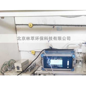 Where to Install an Ozone Moni
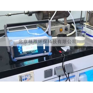 Ozone Monitor Bump Test vs Cal
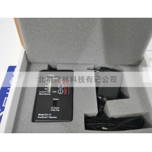 Why Is My Ozone Detector Readi
PPB-Level Ozone Measurement: C